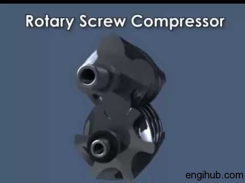
The proper governing of an electric screw air compressor will eliminate many breakdowns. This post will definitely help you a lot if you are using a screw air compressor or rotary air compressor in your engineering plant.
Information shared in this article will apply to all screw air compressors. A compressor may be manufactured by Ingersoll Rand, Atlas Copco, ELGI, and Chicago Pneumatic, it doesn’t matter.
An electric screw air compressor required proper governing to obtain the best performance. Hence I will like to share the detailed steps for proper governing of the compressor.

What is meant by Governing Screw Air Compressor?
01) Automatically unloads the compressor after starting.
02) Load/Unload the compressor at preset pressure limits to match the exact demand of compressed air.
03) Blows down the receiver to a lower pressure at unloading to save power.
So, let’s start the Working on Compressor Governing
01) Load/Unload Pressure
For the purpose of explanation, the unloading pressure is taken as 7.1 Kg/cm² and the loading pressure as 6.8 Kg/cm². This is the standard pressure on which many compressors work in engineering units.
02) Starting with Compressor
Before starting, receiver pressure is zero Kg/cm², hence starting cylinder plunger is extended by spring and servo cylinder plunger is retracted and the butterfly valve is kept slightly open.
03) Working from zero to 4 Kg/cm²
Starting from receiver pressure zero Kg/cm² butterfly valve is slightly open, and receiver pressure slowly increases to 4 Kg/cm².
The blowdown valve is now closed. During this time electric motor is started in the star and switched to the delta, thus starting on no load is achieved.
When receiver pressure approaches 4 Kg/cm² the starting cylinder plunger moves in and the butterfly valve opens fully, loading the compressor. A minimum pressure valve opens only at 4 Kg/cm², the compressor does not deliver air below 4 Kg/cm².
04) Working from 4 to 6.8 Kg/cm²
During this range of the receiver, the pressure starting cylinder plunger is fully retracted and at the same time, the servo cylinder plunger is also retracted keeping the butterfly valve fully open, and delivering full air. In this condition, the blow-down valve remains closed.
05) Working from 6.8 to 7.0 Kg/cm²
During this range of receiver pressure, the proportional controller P2P sends a pressure signal to the servo cylinder just closing it partially.
06) Unloading from 7.0 to 7.1 Kg/cm²
When the discharge pipeline pressure rises above 7.0 Kg/cm², the pressure switch operates. This causes the solenoid valve to open, permitting receiver air to flow to the servo cylinder which then closes the butterfly valve, thus unloading the compressor is done.
As there is no pressure to blow down the pilot pipeline, it opens, lowering the receiver pressure to 4 Kg/cm².
07) Loading the compressor
When service line pressure drops to 6.8 Kg/cm², the pressure switch operates and the solenoid valve closes. This cut off a supply of air directly from the receiver to the servo cylinder opens the butterfly valve and puts the compressor on load.
Now, the blowdown valve pilot line gets pressurized and closes.
08) Stopping of Compressor
When the “Off” push-button is operated, the motor stops, subsequently, the quick exhaust valve relieves the air pressure from the air receiver. Hence a chance of back pressure at the next starting is avoided.
This is all about the governing of electric screw air compressors. I hope, the information above will clear all your doubts and also you can now set the right pressure under the right conditions.
Besides this information, you are suggested to read something more from below engineering books
So, Here you find the Best Engineering Resources for further details
To get the more details about the topic, I further recommended reading
If you like this article, do share it with your friends and also on social sites.


